|
BPH 106H SM106 Restoration 2024A |

|
|
The New Year brought resolution! The offside indicator wire was definitely open-circuit. Dogmatic and filthy work following the stop & tail circuit to its conclusion in the bus-bar cabinet involved separating the thick bundle of wires from its restraints (mostly insulating tape), but eventually it dived under the positive bar and emerged at the northwest corner of a joining plate towards the right-hand end. That was expected from the number of places to which the circuit fans-out, but the identifying sleeve could not be read without undoing the nut and freeing it completely, a process which could not be sustained for the whole loom! Thereafter it was just a case of undoing each terminal nut on the joining plate and checking the individual circuits for a short to negative. By incredible fortune it was the northeast corner and the first candidate. Two circuits were attached: JUN 1 and TAIL. I had already looked very hard at the rat's nest of wiring on the TAIL circuit where it links the rear number-plate lights and bulbs on both sides of the bus, but without finding anything amiss. The implication is clear, however, as the common factor is that STOP, TAIL and OS INDicator run together in conduit....Yes, it was probably my drilling out rivets by the rear blind-box header that cut one wire and shorted two others. "So it goes", as Kurt would say. The search is now on for a route to pull new cables through to replace the damaged ones.
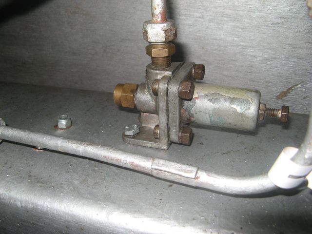
By way of penance, I got down underneath and looked at the handbrake linkage, as I had in mind that there was unfinished business. From now on, the task must be to work diligently toward a complete and working vehicle rather than just pecking away at a long list of structural or cosmetic issues. Putting the clevis-pins back in place was quick, but it wasn't the end. I have never been brave enough to get to grips with my (potentially automatic) slack adjusters because I have never really understood their action and I knew they were faulty (i.e. 100% ratchet-free), but I was given (by Mike Lloyd) a spare brake lever with a functioning slack adjuster and it proved very instructive. In particular, it showed that mine have been modified to achieve a simple, manual adjustment. At first I struggled, but realised that rotation of the inner shell with its ratchet surface was all that was required. Slackening-off was easy, but the worn dogs which engage the worm drive prevented tightening. Thinking it over with a cup of tea brought the realisation that I only needed to take off the powerful return-spring tension and rotation would be easier - and so it proved. Within an hour I had a working handbrake and rear brakes that were more or less adjusted to tolerance. All we need now is a pair of actuators and some air pressure! In my dreams........ A long spell of intensely cold weather then ensued, and when it broke it was still not exactly comfortable, or dry. As proved by the day leading up to Storm Isha while working on the Welsh Highland Railway cutting back lineside trees near to the summit at Rhyd Ddu. Compensation came in the form of a run up the line riding in the cab of Castell Caernarfon, and a visit to Dinas shed where the NG16 locomotive fleet is based and the NG15 is approaching completion. I was astonished by the number of people busy in every part of the shed - a proper locomotive works, in fact. My own efforts on SM106 seemed pretty puny in comparison! All the experimenting with various bits of pipe and connections has taught me a good deal about BSP threads, and the realisation last year that a washing-machine water connector was ½" BSP led to the discovery that a standard hose will screw onto any of my compression fittings on the main air-pipes for testing purposes. A visit to the ever-helpful Dragon Hydraulics at Llandudno Junction furnished the necessary metalwork to fit one (cut) end of my hose to a bayonet for my portable compressor, and an adaptor that gave a straight connection between ⅛" BSP at the solenoid valve and my nylon door-air piping. My first attempt, an elbow connection, fouled the other pipes and was not ideal, despite being a huge advance on the inherited situation. The upshot was a pair of male and female BSP adaptors to push-fit tubing which created a simple extension of the original exhaust air line. No more loud hissing and dumping oil everywhere! Sadly, there remains the tiny problem that the solenoid valve leaks slightly to exhaust, but I am sure we can live with that (until it fails altogether). The washing-machine hose was duly connected to the inlet of the front air receiver and the compressor turned on. In due course, all the loose joints left from servicing the receivers and pipework revealed themselves and were tightened appropriately. My compressor isn't doing enough of what it should, though, so I have not been able to test the pressure regulators properly. I did disassemble the first one which feeds the front receiver at 75psi and found it was as clean and sensible-looking as one might hope. A source of air at the right pressure would be a bonus, but the front receiver was looking good at around 30psi and pressure was confirmed all the way to the EP valve unit on the gearbox. That was enough lying on the floor for one day!
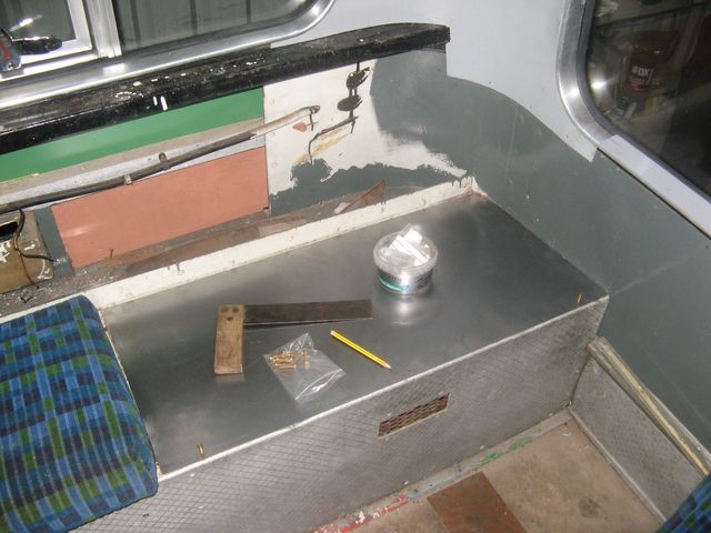
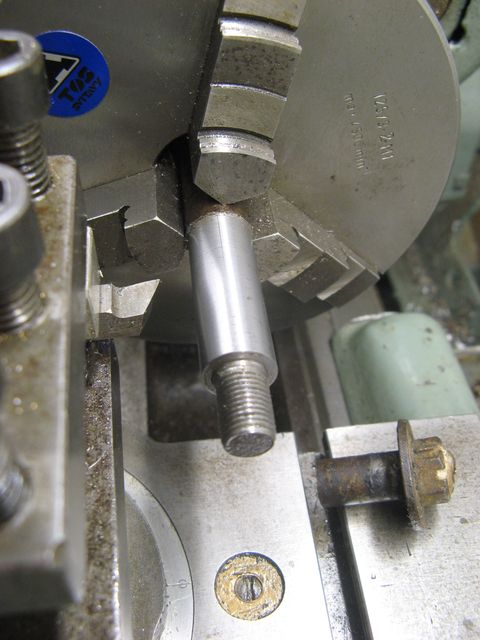
The last weekend of January was unusually warm and I was amazed at detecting a rise in temperature inside the bus in the late morning. Attempts at finding a way through for the new wires to the rear lamps fell at the last hurdle, despite great ease in reaching through the ceiling vents no route downwards could be discovered or created. I am sure it would have been easier before all the panelling was repaired, but that's a view with hindsight. Other tasks proceeded, and the warm weather brought about an outbreak of painting - only primer on the rear of the chassis, but you have to start somewhere. Trimming the edges of the new lid for the offside-rear seat box was a warming task, and fixing holes have been drilled for holding it down. Locating holes for the lugs on the seat-base will be more troublesome because of their size, but that's just metalworking. Work on the air system has progressed, but my compressor is playing-up and I cannot raise enough pressure to test the reducing valves that I have been servicing. Both the valves were found to be in good condition once entry had been gained, which is a good omen, I think. The replacement rear brake-chambers have been dug out of the stores and the links to the brake levers cleaned-up. Maurice attended to the clevis pins many years ago, so they are no longer worn and rusty, but one is tight in the fork-end and needs fettling. The vexatious and rusty condition of the brackets for the bracing-rods to the bottom of the radiator, and their perished rubber bushes also came under scrutiny, and there will be some machining to do on the lathe at home to replace the irretrievably-seized spindles which carry the rubber bushes. Plenty of homework for a change! Sadly, my portable compressor is giving problems of its own, and doesn't want to generate as much pressure as it should. At least, having tried to build up some air, I was able to attach directly to the front-brake line and have the satisfaction of hearing the brake valve operate gradually from the pedal as it should, and then exhaust to atmosphere. I wonder when that last occurred? Sadly, the rear brake line had a serious leak, which was traced back to a crack in the small, corroded pipe to the low-pressure switch. Long disused, these are now redundant and were replaced back in Cornwall days by a duplex pressure-gauge in the cab - which did indeed show pressure on the front circuit.
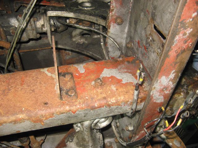
Having been reminded of the terrible, dirty and corroded appearance of the area under the cab-floor, some effort was put in by way of a start towards refurbishment. I was also anxious to see if I could find any sign of life in the STOP light circuit, which originates from a microswitch behind the brake valve. Well, I didn't find any, but it is too much to expect the result one is seeking on the first attempt. On the other hand, the oily and filthy electrical junction box has now been removed, cleaned with de-greaser and put to one side awaiting paint application when warmer days come around again. The other brackets have also been removed to clear the way for aggressive wire-brushing and rust treatment. Fortunately, a second attempt at checking the wiring from the STOP switch gave a much more positive result, which was enough to make me a bit happier on a rather bad day. Having obtained the necessary blanking cap to isolate the faulty branch from the rear-brake pressure-switch, I was very disappointed to find a serious leak to exhaust from the foot-brake valve. After the success of the front brakes circuit, I should have expected nothing less! Looking at the pipes that must be freed in order to liberate the valve for servicing, I was disheartened to see the usual rusty and seized unions, and soon found that my spanner stock was challenged to reach the bits that need turning past the steering-ram and rear drag-link. Even if the force could be applied, I have memories of twisting pipes and the real possibility of cracks in corroded material. Nothing for it but to return to base, and pack for the annual February retreat with my cycling son, this time back on Mallorca.
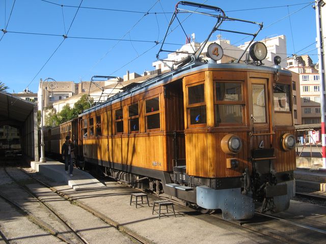
I am no stranger to heritage railways, even overseas, but a first for me was the (almost) century-old, 1200 Volt DC Ferrocarril Sollér. What a fabulous railway, and exceptionally well presented trains and associated tramway. The only disappointment was the inability to find anything even remotely technical about the locomotives and electrification, except that it was completed in 1929 by Siemens Schuckert, and the locomotive carriages were built in Spain. An absolute shoo-in for regenerative braking, and a rather more twisty, narrow-gauge analogue of the fabulous Woodhead line in the UK, the line reaches 199m altitude traversing 13 tunnels on its 27km route. Fantastic! The geologist in me could not live without a trip to some rocks and mountains, the transport provided by the scheduled services of TIB, whose fast and reliable red/yellow buses reach most parts of the island. They look lovely in the sunshine, and are LNG-powered Scania to enable the underground terminus in Palma. My favourite Citaros of EMT in the city are dwindling as they are replaced by by more environmentally-friendly vehicles, but I did see them about and managed a passable picture. A car-park transfer brought me back to Earth at Manchester, with a Dennis Dart doing the rounds - much smaller, bumpier and definitely colder!
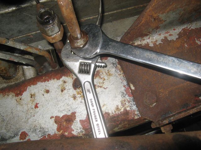
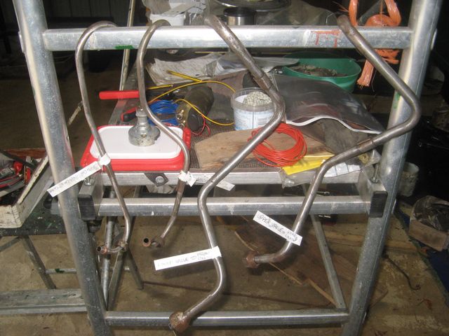
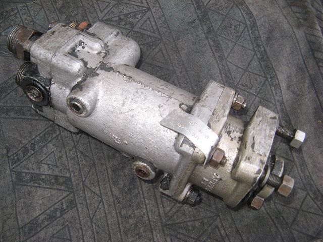
Meanwhile, back under the bus, it was time for a STOP-light switch test with real current. A couple of crocodile clips and a small test lamp were deployed so that I could press the pedal and look for a result. Success, but slightly anticlimactic: the lamp came ON. "So it goes", as Kurt would say. At least I now know that the front-end of the circuit is sound. After that it was time to make with the spanners, and the small-bore brake pipes (to front chambers, and to the rear relay-valve) were soon disconnected. That left the half-inch input pipes, and the real battle was joined. Once I was organised the first came off fairly easily, having remembered to lift the little floor-plate for the top connections. That left the lower unions with the main pipe runs. The main weapon for this task is the specially-modified (Whitworth sized ??) 30mm spanner that was created for the brake-camshaft nuts. I had to undo the saddle-clamp that secures them to the chassis rail by the handbrake cross-shaft, which made room for the spanner heads to engage properly. Then it was just a question of careful, sustained force. The first one was not too difficult as it was well coated with leaking oil from the pedals shaft and oil mist from the valve. The other, less liberally coated, was given a soak with penetrating oil over lunch but proved immobile. Pulling one spanner against the other was just too difficult, given the access limitations. The big adjustable was therefore braced with a lump of wood so that I could pull on the big, shiny one with both hands. Grunt! With feet braced on the front axle for extra oomph it gave up the unequal struggle and turned quite easily once the initial lock was broken. I spent the rest of the session cleaning, abrading and degreasing the four pipes ready for painting at home. That was quite enough for one day, and a huge relief that it had gone so well. Releasing the brake valve once the pipes were clear was a horrid, sticky, oily job, but at least there were no seized nuts under that protective coating. I just need to find someone to overhaul the valve now! I turned my garden shed into a kind of painting booth by putting my greenhouse heater inside, and with artificial light it was quite cosy and convenient. I had a motley collection of pipes and brackets to work on, and the disassembled bell-crank for the accelerator cable. The red oxide was fine, but the subsequent coat of QAD silver enamel was a bit woo-woo because it does pong rather strongly, and there was the added load of fake aluminium parts in GRP (emergency door valve covers and the dome covering the end of the handbrake shaft where it sticks out from the driver's cab). It looked great once painted neatly, and will be a talking point when anybody takes a casual peek under the floor in due course. One of my garage tenants offered an alternative air-compressor, so by the time I had invested a couple of quid in a ¼" BSP male-male adaptor (Dragon Hydraulics again) I had a unit with a good pump and a sensible pressure reservoir. Everything went swimmingly, and it took just a couple of minutes to put a decent pressure on the auxiliary (forward) air-receiver. That proved two things (once I had tightened the door-air union properly): the receiver seemed sound, and the pressure reducer for the doors circuit was functioning. That was good because it showed I could strip-down, clean and rebuild a pressure-reducing valve without wrecking it! Not such good news for the regulator valve on the inlet of the auxiliaries receiver, which showed fresh oil and demonstrated a leak where the steel adaptor had been screwed in too tightly and cracked the cast aluminium body. "So it goes". A neighbour at the garage suggested a contact for repairing the brake valve, so I had to take it to show him, meaning that a bit less oil and filth would be in order - especially as we would be looking for part numbers etc. After a half-hour of coaxing tarmac out of the corners and copious degreaser, something like a valve unit emerged, and sure enough a legible ID tag was attached. A further hour was spent cleaning-up under the cab-floor and freeing the inlet and outlet pipes from their saddle-clamps for freedom of movement and cleaning-up for painting. That is not just a cosmetic job: the front ends of the main air-inlet pipes are not in great condition, so a thorough job is an investment for a future without pinhole leaks. Then off to Alpine Coaches in Llandudno to meet the man - who took one look and said "I recognise that! Space-age compared to that Leyland Tiger Cub across the yard". Whose brake valve he had managed to service a year or two ago....... Pictures duly taken for recording the details, and promised a replacement reducer as well! Fingers crossed. Off for a break in the Lake District next week, so we can leave things to ferment a bit.
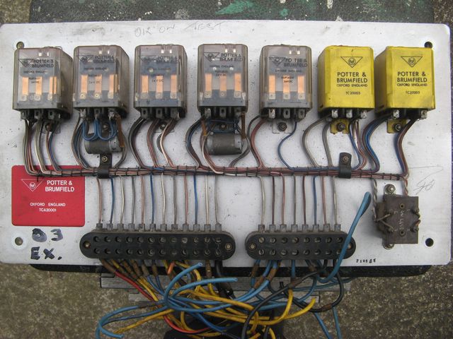
After a week off, I was ready for action, though a period of dry, windy and cold weather has reduced my enthusiasm. But, back at the garage things looked unusually full - another boat has arrived for storage! Even though its trailer has been resident for several months, the bulk of the boat makes a big difference. After further struggles to understand the door wiring, a productive and dirty afternoon was spent continuing the great clean-up beneath the cab, ready for warmer weather and the painting season. I spent the intervening period seeking advice on body-electrics, but without huge success so far. Roger Stagg at London Bus Museum gave me some names, but was not hopeful. He described the awful scenes at Chiswick when the demolition was under way, and how he loaded his car to the roof with papers and talked with the demolition team but found a good bonfire going when he arrived back for more. So far, only initial contacts have been made, but we live in hope. Thank you to all the folk who have taken an interest. In the meantime, I have re-discovered a forgotten item in my father's treasure stash in the form of a spare relay board which is labelled 'Tested' and swapped out from MB171 on 19 Nov 71. That's so brilliant, and not the end of the story since it was recovered from MBS541 in Hitchin. What it proves is that the door controls and interlocks are identical (so far as can be determined) between Merlin and Swift dual-doored buses. The 'power relays' are still available today from TE Connectivity, but the yellow boxes are a mystery since they have no 'closed' contacts in their resting state, and may not be relays at all. I had an email conversation with a support engineer, but he was unable to identify the part numbers. Apparently, in the takeover of Potter & Brumfield there were many (possibly custom-designed) products that were not transferred, and so, sadly, those yellow boxes are now the 'Bermuda Triangle' of vintage door controls. So rare, in fact, that opening one to find out what's inside is not an option. P & B also made complete logic units (such as these, of course) with functions including timers and amplifiers, and my estimate is that they supplied around 4200 door-control units to London Transport across the MB, SM and DM families. The power relays are just sets of three, co-acting change-over contacts with a coil to energise them simultaneously. The connections to the terminal strips have only numbered ID tags, so their destination must be determined by laborious methods. A couple of evenings were spent drawing my own schematic by buzzing-out the wiring. It will help to debug the problem on SM106, though the connections to the outside world were still a mystery, but an inkling of the function was taking shape. At no small expense, the re-manufactured brake-valve and new pressure-regulator have arrived, and can now be configured for installation. I am grateful to RJ Factors and Fleet Parts (Warrington) for their assistance. Part of another day was spent in tracing the wires from the terminal blocks of the door-control panel to the active units on the body. Both sets of doors have a 'closed' microswitch and a solenoid valve, which makes six wires (separate returns from the solenoid) and two more from the sensitive-edge pressure-switch. There are 25 wires to the board (some terminals have up to three wires), and at the end of the process a mere four were unidentified. I suspect that two of them are the transmission feed because they pass through a pair of serial contacts which are opened when the doors are not closed. The other pair is a mystery! Sitting with a cup of tea, I realised that I had understood (but not checked) the action of the air-pressure switch at the exit. The pipes are history, so logic told me that they could not be in an active state, but the truth was more bizarre: the switch was stuck in an 'arm-in-the-doors' condition! When rectified by disconnection, I was delighted to find that the close button for the exit worked a treat. For an encore I finished wiring the 'open' lamp for the entrance, which I had deferred because of rusted screws and all the usual, horrid, corroded things that go wrong with old wiring. The entrance microswitch was hopelessly seized, and non-functional, but at least the wiring is now complete and I could test the connections to the miniature bulb. The rest of the day was spent re-instating the pipework around the auxiliary reservoir and fitting (and adjusting) the new regulator valve. It was off-putting to use metric spanners on the adjustment, but it worked fine, and silently, and it was good to see the doors opening and closing properly again. Then back to the electrics and checking over the wiring through the gear-selector, which has a 'neutral' switch for starting the engine. The source of power to the selector could not be identified, but I know that I have heard the EP-valve solenoids clicking in the distant past; with the generator running to provide a shore-supply of air and 24V there was no chance of that. As the air was warm, the fettled wheel-rims were given a rub and minor damage to the paint caused during the re-fitting of the casings was painted over ready for fitting to the bus. A good day, for a change, and time to read once more the books that I have in case I understand what they are saying, at last!
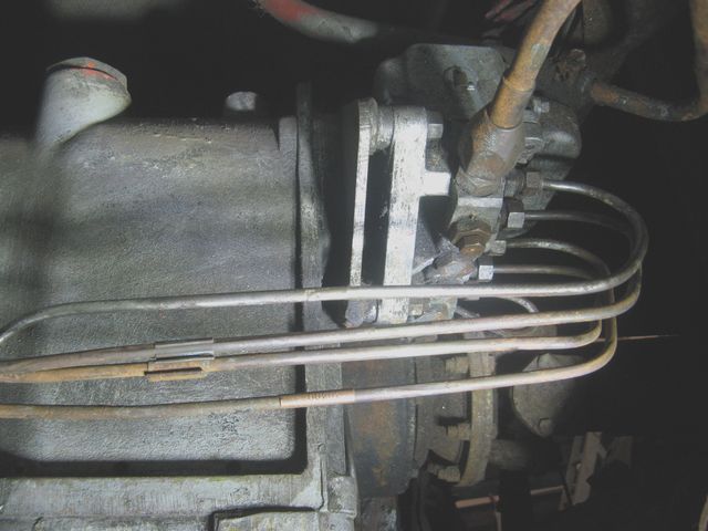
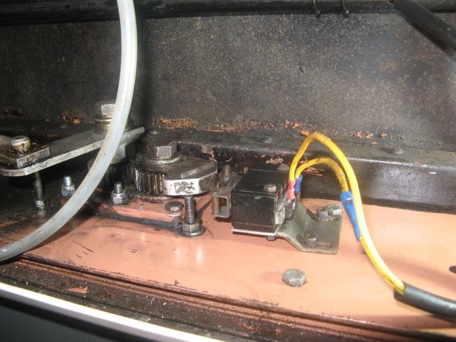
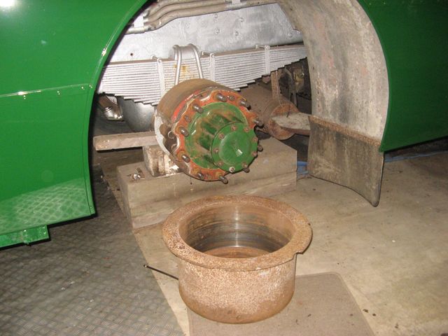
There was still work to do under the cab floor, and rebuilding the bell-crank (now cleaned-up and painted) that connects the accelerator pedal to the morse cable was part of it. During disassembly, it was noted that extreme force was required to push the shaft through the plastic bush, and it was not desirable to repeat the exercise. Being of an engineering bent, I found a half-inch parallel reamer and tidied up the bush. Result, one bell-crank with no shake and a smooth, easy action. It was offered-up but not bolted in place as there was still painting to complete. It lined-up with the morse cable support, so must be correct. The unibal was then applied to the end of the new cable (which has been in stock since 2009) and not only fitted, but the cable moved easily after its long storage, even when still coiled. It has never been installed because it would be in the way of cleaning and painting other parts of the chassis where it runs. Attention then switched to the gear-selector and EP-valve block and pipework, which were cleaned with a wire brush. One of the pipes had been replaced and tie-wrapped to the others, with the old pipe cut off close to the spacing clamp, and a right mess. The clamp is aluminium, unusually, and was impossible to free-off due to corrosion and in dire need of special treatment from a hacksaw. There was a PING, and half of the clamp had vanished without trace. "So it goes", as Kurt would say. I was anxious to separate the pipes to prevent the chafing from vibrations, and found the routing of the first-gear pipe rather odd. Freeing it at the gearbox end resulted in its compression olive dropping out in two pieces, symptomatic of a serious air-leak when in 1st gear! It proved impossible to route the pipe properly, so it was abandoned and the equivalent pipe from the spare engine applied in its place (after a bit of massage and straightening). The pipes looked much neater, and were brushed clean of filth and rust. Eventually, all the pipes were loosened at either the gearbox or EP-valve so that induced leakage would be obvious. Then, with air in the receiver, all the gear positions were tested to see if air leaked as expected. It did! Great celebrations and a coffee-break ensued (no doughnuts or dancing girls attended). Slowly, the barriers to motion are subsiding. I also wanted to rectify the entrance 'door-open' microswitch now that the indicator was wired-in again. It was removed from the filthy header shelf and found to be disabled by bending the actuator arm, which was straightened so that the switch could be tested, and found to be perfect. What animal did that? The effect could be obtained by moving one wire between adjacent terminal posts! A few minutes with a rag and degreaser cleaned-up the header shelf ready for re-population. The cam was fitted to the door support post, with repositioning (turning it upside-down) of the bolt which it fouled, and the whole adjusted to operate the switch as the doors came up to the 'closed' position. More celebration when the indicator light did what it should when the doors were moved manually. Altogether a day to remember and I almost cried when Carly Simon came on the radio singing Nobody does it better as I put my tools away. I had not long sat my final exams at Leeds University in July 1977; Kay and I married in September, and it was nearly the end for SM106 at Leatherhead, of course....... I had intended to have a trip out for a while, and finally made it to St. Helens Museum where I met Mike Lloyd and was reunited with RT1018 which has a special place in my heritage vehicles world, due to a coincidental ride out from Stevenage Bus Garage open day in 1981. Of great interest was St.Helens Corporation 260, a Marshall-bodied Swift, which was over one of the 'pits'. It was astonishing to find that there was no radiator in the usual place, but a pair of saloon-heating exchangers instead! That was just the first of many differences in the chassis compared with the London Transport specification with which I am too familiar by now. A red RT, an RTL and a green RF were also on display, as was an RML, but not as pretty. Just in case I became over-excited, the following day was spent removing the offside rear brake-drum for a clean-up and brake check before re-fitting the road wheels. I also tightened the half-shaft bolts and filled the rear axle with syrupy EP90 oil which has been biding its time on the shelf in my stores. Then it was back to the gearbox, whose top has been cleaned of its thick crust of road-dirt, and the straightening and preparation of the air pipes. The missing part of the clamp was found nestling on top of the silencer heat-shield! Still too cold and damp for a serious painting session. Boo-hoo!
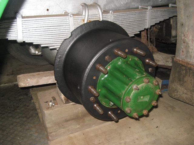
On the next trip to the garage, it was time to deploy the contents of a couple of small Jiffy-bags which had dropped through my letter-box. Irritating was the fact that no vendor I found on the famous web-based 'auction' site could supply BOTH plain nuts and chrome-plated acorn-nuts in 5/16" BSF. The plain nuts were locked together on the stud (ex SMS637 with the gear selector) which was stuck firmly in the rusty, old acorn-nut, and then to drive it properly home in the binnacle. Then both acorn-nuts were tightened to secure the gear selector head, which is now un-wobbly at long last. Then, taking advantage of bright, Bank-holiday sunshine the liberated brake drum was taken outside for a good power-brushing from my angle-grinder, and a coat of rust treatment paint where the shoes don't rub. Warm work! After lunch it was back to contemplation of the air system, and a series of thundery showers which made me realise how lucky I had been until that point! Sadly, extended trials of the EP-valve unit with my apprentice at what appeared to be full working pressure have taken their toll on the entrance door solenoid valve. I had to bite the bullet and work out how to replace it - not a difficult task, you might think. Apologies! This bit has been updated since the first publication of this page. Well, I had to learn another language because pneumatic terminology is quite opaque at first. After learning how to draw what I wanted, and how to read the circuit elements on the web sites of component suppliers, I concluded (incorrectly) that what I needed was a 3/2 NO (Normally Open) valve with spring return. Unfortunately, at that point I had made a mental meltdown, forgetting that it is air-pressure permanently connected between the seals of the ram that closes the doors, not pressure on the control port! Yes, it is a bit counter-intuitive. The Normally Closed version is the simplest valve you could wish for, and that's what is sold to garage-geeks in volume. After a great deal of digging I found just what I was looking for because it even had its ports near the bottom of three of its sides, which made it a square version of the original, cylindrical unit (which had failed in pre-historic times and been replaced by something which is much more difficult to fit, hence my earlier messing around to plumb-in the exhaust line properly). The manufacturer's datasheet said it was available alternatively as NO, but had to be quoted on a special order (luckily the same price) from the retailer. We live in hope, but the auxiliary air-supply is now off-limits until a working valve is installed. Plenty to get on with in the outer reaches of the air system, where after protracted struggles, I was able to dismantle the line between the pressure-reducer valve and the warning switch and test-point. Why do that? It was horribly dirty and needs a clean-up and painting before testing resumes, and there is the longer term issue that it hinders access for cleaning, wire-brushing and painting the chassis. I was reminded that the cross-member that restrains the rear shock-absorbers is rusted through on the offside end - a problem that I had raised and dropped a couple of times over the lifetime of this restoration! Before tidying-up, there was a lot more filth around the front of the gearbox and prop-shaft to clear ready for the opening of the painting season proper. The nearside hub was cleaned, the studs cleaned and given a wipe of grease to deter rust or seizure, the treated brake-drum was popped loosely in place on its studs and the securing bolts popped in their holes. Important, that, because the rear drums and rims don't mount just any old way, this being an AEC and those securing bolts have heads that obstruct rims without relief-holes. The idea is that you remove them and insert into threaded holes in the brake-drum to jack it off progressively (until the threads strip because they are so short). |
|
BACK .......to the index. |
FORWARD .......to continue the diary. |


