
|
BPH 106H SM106 Restoration 2020A |

|
|
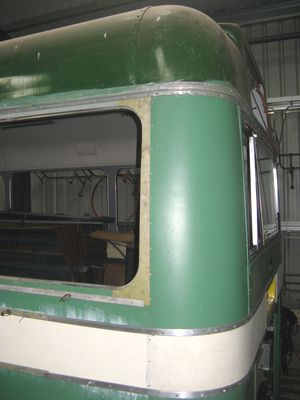
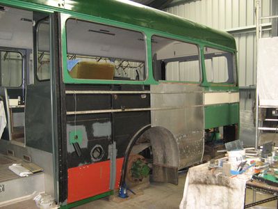
We are acutely aware that this year marks the 50th anniversary of the formation of London Country Bus Services, and also the entry to service of the Park Royal bodied AEC SWIFTs, the new company's first new vehicles. However, this new year did not bring any big change in circumstances, but an increased sense of urgency and determination to grapple with those thorny issues - especially as this is SM106's golden jubilee year. One of those critical issues being the stress panel behind the exit door well, an important item relating to the strength of the body in an area which was a source of structural weakness in the predecessor Merlin MBs. I don't want to bolt it all up until all the nasty rust is treated in the framework which would be obscured by the installation, so until the weather warms ready for paint-type treatments it will stay on hold. That means progressing the panelling behind the rear axle, which was well underway before Christmas.My predecessor, Steve Fennell, was good at finding spare parts, and one of the many items recovered from SM533 was a great deal of beading from the bodywork. Sadly, a lot of it is almost useless because Metro-Cammell used a standard drilling pitch of around 4.25" while Park Royal used about 3.5" - actually neither is a rational dimension in either imperial or metric units! Maybe the more frequent fastenings are the reason behind the relative longevity of PRV bodies compared to MCW? Anyway, the big issue is that you cannot fit MCW beading to SM106 because none of the holes will line-up, and the beading holes are effectively the template for drilling the panels in the correct place for rivetting. Well, I suppose you could, but it would not be kosher, and the steelwork would be more like a sieve than it already is. However, using short lengths is OK for all those crazy little pieces that make up the vertical elements of the bodywork, some as short as 2.5". The trick is to pick a strategic rivet-hole and cut the appropriate length, drilling the couple of new holes which will be necessary and countersinking and filling any old holes which remain. It almost takes longer to desribe than achieve, and once again it's all basic and quite enjoyable benchwork, which CAN be done in colder and damper conditions, and it really counts because the modern pattern of beading is thicker and sticks out like a sore thumb when alongside the original.
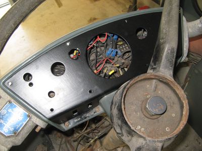
I also decided that it was about time the driver's binnacle was rebuilt - not entirely simple because of the difficulty and damage sustained during dismantling. The fixing screws were heavily rusted into the steel nuts held captive by embedding in the GRP moulded case, and one needed replacing somehow. With that job done, the metal fascia which was painted-up last autumn could be offered up and a set of screws found from stock. Another little amusement was doing some metal-bashing (literally) to see if a second-hand aluminium front corner panel could be attached. I have no idea where Steve obtained it, though Central Area obviously, and very possibly a DMS. It had evident 'patina', but it looked a great deal better after some careful attention, and attached prettily without much fuss, and it was making a new length of beading to cover it that started me down the road discussed above. Purists may argue that the corners should be in rubber, and I do have some, but in such poor shape that I am reluctant to try and fit them. All this work brought an unwelcome focus on a less than ideal fit of the trim panel at the rear of the window in bay 6, which has had a long history of abuse during successive attempts at finishing the curved corner panels. It was decided to make a new one - not difficult if you have a jigsaw - but my stores could not supply the thin sheet required. Casting around, it became obvious that the necessary material was literally lying on the floor, in the scrap pile. Parts of one of the old sheets were in very good condition, so it was taken home and cut out ready for finishing on-site. It was a survivor from LCBS days, with PRV pink primer on one side and traces of canary yellow highlights on the other: a 'heritage' panel no less! Exactly what the primer technology on the 'green' side was, it is really deeply etched-in and impossible to remove without sanding through to clean metal - a great thing, no doubt, and a good start to preparation for painting.
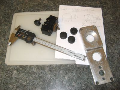
Meanwhile, back at home a search for some obscure item happened across an ice-cream tub full of bits from another long-running saga: the door-operating switches. Occasionally, when a dark mood descends I look for something small and technical to play with, and back in 2017 (I know this from the dates of pictures) I was looking at the sorry mess of seized-up and grotty door switches which were removed from the driver's-elbow panel so it could be painted. One had a cast aluminium body, while the other was a horrid piece of moulded plastic. Both had at least one microswitch assembly stuck in either a down or up position. A search soon found one that Maurice had removed from MBA541 in Hitchin along with other electrical panels and units of potential value. It looked as if it had been in front of an open (or leaky) window for a long time and regularly filled with rainwater, but the aluminium casting was fine and the microswitches worked. The trouble was that it could not be disassembled for spares without removing the push-buttons, which were held with tiny, socket-headed grub-screws which had long ago rusted into absolute immobility. Eventually the only way forward was to break one of the buttons which could not be freed, and the great clean-up started. The castings also carry a door-open indicator lamp unit which were also in poor shape and missing their bulbs. Finally, when the situation was proven to be recoverable, the only big problem was the shortage of one button.
This seemed like a job for Lottie the Lathe, and an inch round bar of black PEEK plastic was obtained through the usual online marketplace. Offcuts from engineering works are a profitable business for niche suppliers, and prices are very good if you are careful. The prototype was promising, but unsuccessful. It took most of a Saturday evening to turn out the first production button, and Inspector Meticulous might have looked askance at some of the contortions that Lottie endured while shaping the domed head but it looked and functioned well. Machining soft stuff like PEEK probably allows a tyro to get away with things that would not work in steel or brass. Another evening was spent disassembling, cleaning, testing, replacing bulbs and generally having a good time in a warm environment. End result, the promise of a pair of door operating switches to die for, assuming they can be fitted to the bus successfully. My hunch is that they are both MB parts, but I don't care and the more recent plastic part is an abomination. Well done, Maurice, for saving the crucial bits. The next trip down to see the bus was just a bit more of the same fettling work on panelling. For a long while the panels in bay 5 have been held by pop-rivets to ensure that they would not flap when SM106 was moved to the new garage. At last it was time to release them so that they could be adjusted for size and overlap, and set up the cut-outs which allow the overlapped panels to lie flat under the beading. Then the last part of the vertical run of beading was addressed. Just like the pillar which runs down the rear of the engine bay this panel simply laps onto the steelwork, and as a consequence the lip of the beading must face the aperture. This time there was no ambiguity since convention has it that panels overlap their rearward neighbour. Bearing in mind the shortage of 'PRV' beading, I decided to try a piece of MCW beading that was close to length and discovered that with care the original MCW fixing holes could be used without interference from the existing PRV holes. The difficulty came when the panel had to be drilled 'blind' to start the process off (the composite 'top-hat' section of the bodyside pillars do not allow access from behind). So a bent scriber was improvised from a length of stainless steel from a cavity-wall tie that was lying on the floor when we moved in. With the panel in place the scriber was pushed up the hollow 'top-hat' and jiggled comprehensively about in the fixing hole, marking on the back of the panel the position that should be drilled. Of course, this compromised the PRV-purity principle, but so it goes (as Kurt would say) and I don't suppose anybody will notice down there.
One objective in the restoration of SM106 is the return to early service condition so far as practicable. We have mentioned the status of the public-address system in the past, and questioned whether the parts were ever fitted. It is certain, however, that the boxes which contained them were fitted, because the fabulously detailed and valuable PRV record photos of SM119 show the boxes in place in the upper and lower leading windows, bays 1 and 4 respectively. Equally certain is that the boxes were not in place when I took over the vehicle, because the nearside window in bay 1 was an incorrect duplicate of the proper bay 2 style, and photos from various sources show that the speaker grilles were neatly panelled over at a very early stage of her afterlife in Cornwall. The window in bay 4 behind the exit is still in place and without its box. When I collected all the seat cushions from my HN fairy-godmother I was fortunate to acquire also a pair of fully-populated top-slides with complete speaker assemblies. On another recent, rainy day I set about disassembling one so that I could reinstate the grille and box in bay 1. The alternative, of removing the window, and exchanging the topslide is not a viable option. Even taking the whole aluminium frame off the glass is not a task for the faint-hearted (see previous experience for why), and splitting apart the components of the frame unit is a virtual impossibility due to the usual reasons of corrosion and weakness of self-tapping screws. The box itself is the usual GRP moulding, held to the window panel by countersunk screws and short, wooden battens. The rusty screws were easy to undo because their remains self-destructed under screwdriver torque. At least all these parts are easily replicated! The speaker is a monstrous, metal tannoy unit, and will be consigned to the museum stores. If you have need of one, just give me a shout. The removal of the strips holding the metal grille (which was in perfect condition) required an angle-grinder to cut away the frozen nuts. Eventually, the grille and strips arrived at home for processing, which didn't take long. Time-honoured aids such as scotch-brite, wet and dry abrasive paper and a bit of detergent were quite enough, and after a coat of primer or satin black spray paint we were ready to start re-assembly. A small detail, but another box ticked for authenticity. Another, important point to take away is never to underestimate the strategic value of the humble, wire coat-hanger which can be pressed into service in a great number of critical roles, including as a drying-rack for painted, small parts. Recently I came across two pictures of SM106 which I had not seen before on the Flickr web site, posted by Michael Thorne. I have not come across his work before, but it is excellent and wide-ranging in its choice of LCBS and LT subjects during the mid-to-late seventies. He has images in his collection of many of the PRV Swifts and one of SM106 operating on the legendary race-day service 406F at Tattenham Corner. As I followed (on Google StreetView) the modern roads covered by that route I was struck by how quickly Epsom town disappeared and what an extraordinary area is Epsom Downs, a massive contrast with the length of frankly dreary suburbia on the Kingston leg of the full 406 route. Somehow, I do not see much threat to this area of the green-belt! It also seems amazing that a double-deck bus (RT or RML) would traverse the Downs every 15 minutes from 8am to 8pm Mon-Sat with many more at weekday peaks. Although my (so-called) Aunty Amy and Uncle Alf lived in Epsom in the 1960s, I have never visited the town except for one journey on a 470 back in the mists of LCBS history. I do recall boarding the RT at Hamsey Green, and buying my very long Green Rover ticket from a real conductor with a Gibson register, but that's about all. By the time red Swifts operated the 194 route they were living in the flat over the Westminster Bank in Shirley, and Aunty Amy had nothing good to say about the new buses. I could hardly tear myself away from the upstairs window, amazed by the sheer frequency of new SMS buses at their front door! However, back in the real world it is obvious that the chassis and underfloor framing of SM106 still carries a great deal of rust to bust, but cold weather is anathema to painting the resulting clean(er) metal. In fact, my chosen rust-converter paint says that it should not be used at temperatures less than 10°C ! So, in my latest work session I concentrated on removing the piles of road-dirt and loose chassis paint, and started to detach the remote air-cleaner, which is in the way and defective due to loss of base and filter media. You can see the oil-bath, Burgess-type air cleaner in a picture higher up this page. It is a hefty chunk of metal, and may well prove to be a difficult item to repair. The amount of muck that descended from the air-cleaner and the hose to the inlet manifold was awesome. I suspect that cleaning out the air-hose was probably one of my most constructive activities for a while! I also jacked up and dismounted the nearside rear wheels so that the greatest length of chassis would be presented free of encumbrance. That was hard work, so I set about undoing the rusty and reluctant screws holding together the second 'speaker-box' which will go to the bay 4 window top-slide in due course. With both boxes in progress, an element of mass-production will pay dividends. Fiddling with fibreglass mat and filler was very therapeutic after struggling with headless screws for too long, but in the end I had a pair of fettled, clean boxes painted in grey undercoat. By then the sunshine had warmed things up a bit and you don't find condensation on GRP. It was also good to have company, all but one of the garage tenants having turned up during the day.
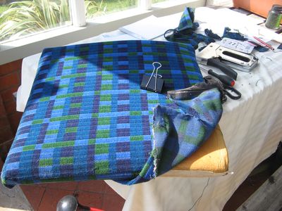
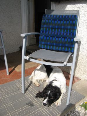
I received an email the other day from Justin Vella on Malta, who is doing his best to resurrect MCW-bodied SMS736 which is one of the number that ended up parked at Pembroke as Christmas-trees, and because of doing little active work is in remarkably original condition. He was asking about glazing rubber, which is fairly important as his buses are in the open and have been robbed of windows, so replacing them has been a priority. Not many MCW-bodied vehicles remain, but I'd say that the owners of the three that I am aware of could co-operate and have new weatherstrip made without inordinate cost. Justin's enquiry sent me to my catalogues of body parts for MCW and PRV buses, and it turned out to be an interesting delve. Many parts from external suppliers had no LT-type part number, while a significant number of parts are listed as MBxxx (no great surprise) or even RF864C1 (for example, which is a 'Stencil Slide', or running-number holder in plain English). Against MCW bodies List XB176 (Arrangement of Side Frame Complete, n/s) there appears "Glazing Rubber HRC X5610 as Req'd", while for PRV bodies the part is given on List XB174 as "Glazing Rubber HRC X5193 As Req'd" with a modification advice to "Glazing Rubber HRC X9316" at some point. HRC appears to be abbreviation for Hertfordshire Rubber Company in Works Road, Letchworth Garden City, who were major suppliers of rubber seals to the automotive industry from at least the 1950s until 1977, and of particular interest is their Glazetite Self Sealing Weatherstrip. I am sure that Paul Brophy told me about a bus that he had seen which had inside boxes of glazing-rubber marked Hertfordshire Rubber, which makes sense. Sadly, as you might guess HRC was acquired by BTR and production transferred to Dunstable before closing down. Letchworth was not only famous for corsetry and computers (my first 'real' job was at ICL) but a centre for surprisingly heavy engineering, host to Kryn & Lahy who were in armaments manufacturing during WW1 and run largely by Belgian refugees. Later this business became K & L Foundry and finally Jones Cranes, whose KL models were widely appreciated and originated in the Garden City. I think that we had better find a 384 and explore Letchworth. I was completely unaware that London Transport served Letchworth until one day, quite by chance, on a 1960s bicycle-ride with my friend Kenneth we passed the railway station and there was an RF bus standing on the forecourt. I had seen the 383 going past Willian Pond, so there had been no need to investigate the presence of reassuring roundels on the bus stops. Although I did eventually reach Weston on a 383, I never travelled on a 384 to Letchworth, the route being an unattractive dead-end, though the Hertford leg was considered. The other problem was connections at Stevenage, which were not favourable, and the flesh-pots of St.Albans or Watford were more attractive. I am sure that nobody needs an explanation of the trouble that Covid-19 has caused the world of bus preservation, or any other distressing side-effect of the campaign to ameliorate its potentially fatal consequences. Suffice to say that going to work on my bus did not class as "key-worker" occupation, or even personal exercise from home. Some work on the project did proceed because bits that I had brought home had lain untouched for a more or less long time. First off the blocks was completing the modification to the single-seat cushion that I was modifying from a spare double. Having equipped myself with the necessary strong upholstery needle and linen thread, I had to pluck up courage to cut the moquette, which the reason for the long delay. I have very limited skills with fabrics, but in the end I reasoned that there was actually a lot of spare stuff at the garage and it would only be a nuisance if the cuts went wrong, though there must be a limit to the number of times one can remove and re-staple the cover without wrecking the woodwork. Once started, it seemed to work out OK and the problem that I had was erring on the side of caution and thus not stretching the fabric sufficiently tightly. I also made a paper template to remind me of the cuts that I was trying to achieve. All a bit of an overkill if you are skilled, but I was not. After a couple of false starts I began to get the hang of it, and ended up undoing one of the original corners because it was such a mess and relied upon just a couple of thick wire staples rather than sewing. In the end it looked OK to me, and probably won't be noticed by my passengers. I must say it made a very comfortable back to one of our porch chairs.
The other job was to do the repairs to the emergency window catch assembly. The prototype process had been successful on the spare unit, but had to be rolled-out in production on the primary unit, drilling and tapping both pivot pins before fitting new bolts and dome-nuts. The primary unit was chosen because the chrome-plating on the handle is better, and the link-rod less rusty. Eventually the link-rod will need painting black, but that was best done after the engineering. It was simple enough to drill the new holes for tapping, this time catching the dog or interior handle in the machine-vise, which turned out to be safer, just as secure and (probably) more vertical. Drilling and tapping was fairly straightforward, but I had to do a bit of careful measurement in order to prove that the tap had reached the bottom of the blind hole. Trying to drive it too far and snapping it off would be an A-grade disaster! It all worked out OK, but then the process ground to a halt because the emergency window frame was not also at home. So, then we had to contemplate a mission to compensate for the lack of Transport Festival this year. Please don't tell Mr. Plod what I was doing.
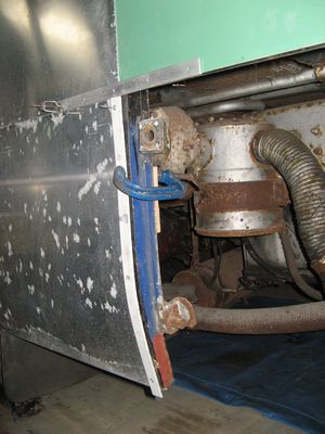
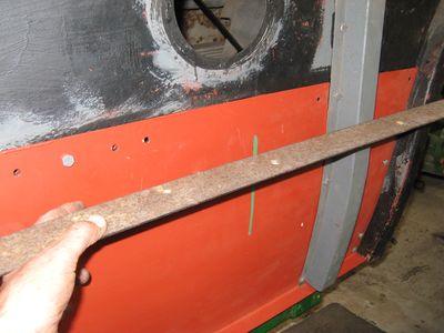
The first job to resume was treatment of the rusty framing under the floor to the rear of the exit well - if you recall, this job was on hold because the rust treatment said not to use with temperatures less than 10C. It tells you how long ago that was! Inside the garage the temperature was almost too warm for comfort, so strong was the May sun. The wire-brushing had all been done earlier, so it was more or less straight underneath with a tin and brush. The results are shown, not pretty, but that's not the top coat, and I included the untreated, upper stress panel so you could see both before and after. When that area was completed it was lunch-time. The rest of that area will be done with the chassis as a separate campaign. After lunch the first task was to complete the removal of the air-cleaner. Three out of four bolts on the strap came undone, the fourth was cut off with a hacksaw. When it let go there was an avalanche of dried, silty mud from everywhere around. Mud also lay on top of the chassis member 40mm deep - clearly the general spray of road-dirt from the rear wheels has not been washed off for most of the life of the vehicle. You can see some of the pile of filth after I swept the floor. The air-cleaner poses an interesting problem, because it is going to be a big job to clean up, but the base is missing and there is no point trying until I have a complete unit. I suspect that she operated for a long while without it, given the state of the air-inlet pipe.
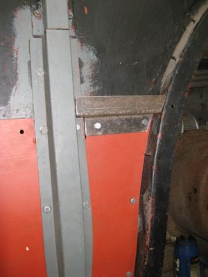
With the rust-treatment paint dried, it was time to fit the new stress-panel. The long down-time meant that I had forgotten how it all fitted, but the kit did not have many parts and it was soon coming together nicely. I had a scare because the new top-hat section pillar was sitting well proud of its proper location, but then I realised that several of the bolts were still loose, and tightening them brought things nicely into line. I even ran my straightedge between the wheel-arch and exit door pillar to check, and it was just fine. I also realised that I had the bolts in the wrong way, because I forgot that the 'outside' view is actually the inside of the gap between stress panel and the 'skin'. It was also interesting that the pillar was in the right place despite the interposition of 1.5mm of steel, so I think somebody knew what they were doing and I have just completed the puzzle correctly. It isn't plain sailing, however, because there is an intermediate Z-section moulding-rail which carries the joint between the outer panels. Because the new steel stress-panel sits on top of the metalwork attached to the exit bay pillar, rather than rivetting into it, the inherited (and possibly remanufactured) moulding-rail is too wide. A new one has to be made with a taper, so that there isn't a bulge in the panel when it is fitted. I think I can imagine a way forward, but it requires a competent welder to assist. Bu**er Covid! Luckily it is not the most highly-stressed part, although flexing of the body around the exit aperture was the weakest part of both the Swift and Merlin buses. Exhaustion was setting-in, so I had to gather the parts for home-working and leave. It's an interesting note that the parts list of body pillars include what are termed "repair sections" but exactly what they comprised is not explained, though it makes sense when you consider the vulnerability of the valance area of the body.
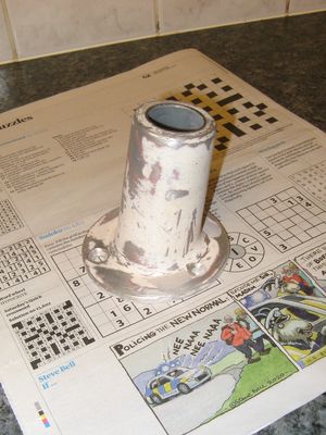
One of the pieces of homework was not particularly taxing. The seat-back stanchion on the rear of the nearside single seat has been missing since the seats were rotated and moved forwards by Blue Lake, which is a shame because it is unique to this body type. Standee buses did not have seat-back stanchions in the lower saloon, they had thicker ones from floor to ceiling, and all the ceiling sockets were in a straight line along the intermediate beading strip. Because of the narrowness of the single seat, the stanchion was closer to the window than any other, and the slope and curvature of the ceiling necessarily greater. The loss of this unique ceiling socket is therefore a blow. Blue Lake, in their wisdom, did provide a stanchion in an alternative, offside, non-prototypical location, and made a right mess of the ceiling in the process (we will come to that in due course). I have a large collection of stanchions and sockets from the MBA donor, and one extra socket with an incompatible part number stamped on its base. It has a more oblique tube than the others, and is thus a better starting point for modification - BUT it has four fixing holes. All the normal MB/SM sockets have three. I have no idea where it originated, but it needed converting to three-hole specification to fit the ceiling where there are still the original fixing holes in the ceiling above the single-seat back. Luckily the holes were arranged in a 'diamond' pattern, not a square (probably stronger as there are three unique fixing lines, rather than two) so it was possible to use an SM-pattern socket base to mark the correct drilling positions. Geometry dictates that if you line up the master hole (adjacent to the longest side of the conical tube) the set of three holes will not coincide with any hole from the original four. Off to the drill press after filling the unwanted holes with body-filler and cleaning up. Drilled in no time and countersunk in moments using a large, long drill-bit to reach into the holes, only one of which can be reached with a conventional countersink bit. Job done, and time for tea. To finish that job we have to design a packing-piece to accommodate the different ceiling profile in its new position, which will not be simple. Apart from anything else, we need to fabricate a stanchion long enough to use as a jig to align the socket properly.
Determination to make progress on the stress-panel and its associated moulding-rail over-rode other considerations, so a day was spent on the nearside Bay 4 in PRV parlance. One job was to take out and reverse all the bolts holding the new stress panel and its pillar in place. - done progressively as relief from other tasks so as to avoid boredom. There is complexity in the moulding-rails for all the rear bays because they cross the intermediate pillars and are thus divided into front and rear parts, and the pillars are not spaced equally due to forming supports for the body adjacent to the wheel arch and carrying the detachable valance panel over the engine. The Bay 4 moulding-rail comprises a short piece just 4 inches long, and another over 2 feet long. Both are now compromised by sitting on top of the extra metalwork, particularly the forward end of the front part. Giving the short part a good seeing-to proved that it was a shocking bodge, packed with filler and carrying the creeping plague of excess fixing holes from re-panelling in the past. It had to go. Luckily I have a scrap stress panel from the first, unsuccessful attempt, from which a small rectangle was cut and a pair of bends formed on the 'ship', which had its first serious outing since moving to the new garage. I was a bit nervous about working on steel rather than aluminium, but it turned out to be a piece of cake making the first, simple bend. Using the geometry of the first bend, I then had to set up the critical operation of making the next bend on a slight taper so that it would take-up the variation in thickness across the stress panel and fixings. Fortunately I had made the measurements correctly and it too went according to plan. That was worth a cup of coffee, taken while fettling all the weird angles and cut-outs necessary for interface with the pillar and wheel-arch. Finally the spare material was trimmed off neatly parallel to the first bend (just so it didn't look cock-eyed, which it wasn't). Then it was offered up and drilled to match the stress panel for fixing, and given a coat of rust converter as a primer. I hope that works. Other tasks performed were removing the Bay 4 window and applying paint stripper to the gutter moulding and environs, cleaning-up the forward window trim, rust-treatment and installation of the adapter for the saloon heater air-intake and measuring-up the required modifications to the forward part of the moulding-rail. After a bit of grounds maintenance it was well-past time to depart. A good day!
A second, short session of work on the clean-up of bays 4 and 5 saw the gutter-moulding and window panels under attack from paint-stripper and carborundum paper, so that by the end of a busy afternoon there was no paint left anywhere, and serious consideration could be applied to the build-up of the restored livery. As the gutter moulding also needs painting, the gutter had to be cleaned, and with it the accessible portion of the roof all the way from the exit to the rear-end. The amount of dust and filth was quite surprising! A couple of days later (a special opportunity as we should have been on holiday in the Lake District) after time for drying out and the dust settling an extended session was devoted almost entirely to painting. First an etch-primer to the clean metal, then a coat of green undercoat to everything that was ready. Part 2 of the session was spent underneath putting a grey undercoat over the rust-treatment. That means that the under-body in bay 4 is ready for silvering, though I think it will wait for some more of the chassis to be ready. Back at home the work on the emergency exit window was progressed, nuts and bolts being prepared for the handle and catch fixings, and the link-rod on the catch cleaned up, primed and top-coated in black. Unfortunately, I have so far been unable to find a suitable replacement for the air cleaner. The DAF part which looked so good in the catalogue had an exit hose 145mm in diameter, which is way too big!
Two coats of primer/undercoat are a minimum, I reckon, so another day was spent on painting tasks and general tidiness. As always there is lots of that to do! After cutting the bay 4 moulding rail along one side of horizontal web, excess metal was removed with my angle-grinder and a file - then delivered to North Wales Engineering for welding back together with its new dimensions correct for the tapered stress panel area. Still at home, a second coat of black gloss was applied to the emergency window catch assembly. This is an exciting moment - I can think of no big technical issue that prevents the completion of the nearside bodywork, although I have an uneasy feeling about the fit of the engine access hatch. This seems like a good moment to move on to another page, especially as it is now the end of May. |











|
BACK .......to the index. |
FORWARD .......to continue the diary. |