|
BPH 106H SM106 Restoration 2019A |

|
|
The cold, dark months are not good for working on buses in unheated sheds. Tidying some of the last jumbled residua from the Trefriw garage evacuation, and landscaping works outside have been the limit for a good while. However, moves were afoot to work on the last major bits of bodywork ready for completing the paneling at the nearside rear. Certain jobs need completing first, such as the lower stress panel in bay 4 and the minor corrosion pits in the upper stress panel near to the window pan, and the re-mounting of the exit doors emergency release valve. Until paint-friendly days return they are on on hold. Tidying and sorting the stores is never on hold, unless darkness has fallen! So, the pile of assorted handrails in a corner found that its day had come. Blue Lake, in their wisdom, had done a lot of messing-about with the bits of the bus which people grabbed onto to steady themselves, but before we start some terminology must be refreshed. A handrail is more or less horizontal, while a stanchion is approximately vertical. Stanchions on a country Swift run between the seat-backs and the ceiling, apart from two which run from floor to ceiling and one which stands at the exit so people waiting to alight don't fall down the steps to the road. Both the floor-mounted stanchions are 1¼ inches in diameter and both were hacked by Blue Lake to affix low-level bell-pushes. The stanchion at the rear of the longitudinal bench seat has already long been replaced with new tube. Low-level bell-pushes were also fitted to all but the rearmost, offside seat-back stanchions. This means that there is a deal of work to complete before pristine stanchions populate SM106 properly once more. So how to work out which bits of metal belong to SM106, and which to donor vehicles such as MBA? On the face of it, anything with an angle-grinder slot must have belonged to SM106, but confusingly the lower end of one of the 1" stanchions matched those assumed to be foreigners! Because that particular item was too long to fit anywhere except the lower saloon, and wasn't present on the nearside in Keith's pictures from Southbourne, it follows that it must have been attached to the foremost double seat opposite the exit. Odd! The other notable feature of the 'foreigners' was that the complex threaded thimble on the lower end would not undo, unlike those which appeared to belong, which have a tiny pop-rivet to prevent the thimble undoing in service. Cutting one of the foreign thimbles open revealed a very interesting, and complex bit of engineering. A mild-steel insert is rammed up the inside of the swaged stainless stanchion tube, and it was the rust formed on its threaded section which locked the stainless thimble in place. This suggests that the rusty threads were a historical problem to London Transport, leading to a change in later vehicles where the swaged stainless tube is threaded externally and simply screws into the thimble. Simpler, cheaper, non-rusting and easier to maintain. Unfortunately, the body parts list talks about the different seat-back stanchions in the saloon, but does not give them a length, so there is guess work attached to ascribing them to location. It does appear, when counted, that there are more stanchions than I need, and at least one to replace each of those with ground-out slots. I suspect that donor vehicle SM533 may be behind this supply of spares, in addition to MBA, and one can be reallocated to the lower saloon where some welding may save the day. One obvious point is that the tube used on the SM and MB vehicles has a thicker wall than was used on the later DMS - just ding the tube with a coin or such to HEAR the difference! With a number of MBA stanchions to provide spare tube (one already used of course, in the luggage pen), the situation looks promising. The fixing of the emergency exit window and the state of the release handle have long been a concern. A good while back (er, 2013, I am sorry to say) I mentioned that the support blocks which hold the hinged glazing frame had suffered from their dismantling before my ownership. As usual, steel screws had rusted into immobility, and the heads of the countersunk screws were drilled off to release the window for replacement. I still don't know how the glass was broken, because it was in one piece when recovered from Emsworth. The documented attempt to plug the holes with 'metal' epoxy compound was a dead-loss. Far too soft. Messing about on the Web one day I was reminded of the helicoil insert, and set about finding some at 2BA, which was easy enough on eBay. It turns out that the repair drill size was 5mm, which is about what I had after drilling out the rusted remains. A couple of days later I set about the repairs to the support blocks. The tapping drill turned out to be superfluous, which I expected, but the tap found something to bite into and the inserts screwed in fairly tightly. I didn't have a 2BA tap with me, and it would have helped a couple of the screws find their way properly, but overall it was a huge success and six refurbished holes awaited their new (stainless) screws. I know that there are strength issues about stainless, but this job isn't about strength, or indeed cost when you consider the time involved in repairing rusted screws.
Now, I never expected that I would ever write the following, but it's all true, and possible because I have inherited Maurice's lathe, tools and materials, much of which went into temporary storage at LL. So, faced with snapped-off dome-nuts on the emergency window catches I concluded that drilling and tapping the remaining metal to provide a new fixing was the way forward. The two dogs which lock the window have ½ inch studs welded on and the assembly is chromium-plated for cosmetic reasons. A flat bar is rivetted onto each dog so that both are turned by the internal or external handles. The stud holding the handles (see above) is longer so that it can accommodate the external handle. The studs, which used to have threaded ends, pass through the window frame and were secured by plated dome-nuts. Initially my angle-grinder was used to remove the remains of the sheared-off threaded portion of the stud and create a flat end. Finding the centre of the studs accurately isn't simple, so I decided to make a jig (or dolly) to find it and ensure concentric drilling. A piece of aluminium rod an inch or so long was soon located in the materials box, popped in the lathe chuck and faced off, then centre-drilled three-sixteenths to a decent depth. The part was reversed in the chuck, centre-drilled again to ensure a clean start to drilling out slightly under-sized for most of the depth. The rough hole was then cleaned-up with a half-inch drill and Bob's your uncle, a dolly to slip over the stud and find its centre. Whether Inspector Meticulous (or my late Uncle Leonard, model engineer extraordinaire) would approve, only Curly** could tell. One cup of coffee later, the catch assembly was set up on the pillar drill and packed carefully so the studs were vertical. Luckily the dogs are wide and flat on the other side. The dolly was placed over the first stud and the same centre-drill run through the axial hole into the stud to get a nice clean hole, which was then opened out tapping size and tapped ¼" UNF. This was then repeated for the other stud, which has a squared end for the external handle. Sadly I didn't have a bolt to test the threads, but I have faith! The way forward is to take appropriate, stainless dome-nuts and tighten them onto another bolt, cut off the spare head and trim the length so they tighten snugly into the studs without gripping the frame. Engineers will spot that because the holes are blind, at least part of the thread will be tapered at the bottom, and thus provide grip. Quite adequate for Class 5 purposes, I am sure. Now, all of this was an experiment on the spare item, so it must be repeated on the real thing in due course, but at least the experiment could proceed without damage to a very precious part indeed, especially as its chromium plating is in much better condition than SM106's original.
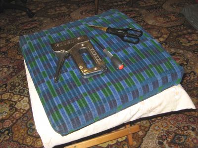
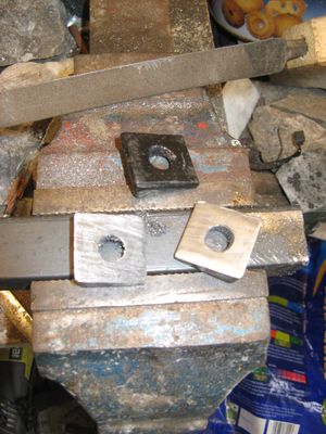
The popularity of the Great British Sewing Bee on the Beeb has a lot to answer for. Way-back in 2013 I experimented with cutting down a two-seater squab (the back of the seat) to replace the one which is missing from my second single seat. Now it was time to finish the job (I didn't cut any fabric because it is too precious), and of course I have received an Espace-full of Celestra cushions and squabs from my Fairy Godmother in Hertfordshire to re-use or cannibalise as necessary. First I had to make a new edge to the wooden board, which is curved and carries a projecting lip that locates the squab in the frame aperture. Once fettled it was set aside for glueing at home. Next I had to cut the firm edge off the Dunlopillo foam filling and re-attach it to the narrow item, soon effected with a bit of Thixofix. That was the end of work on site, as all the necessary tools were at home. The offside single squab was a very sad affair, worn, dirty and flabby, so it obviously needed refreshing too. Removing the cover revealed a disgusting mess of yellow, gritty powder which spread everywhere. Eventually I was left with a wooden back and a lot of blue tacks with tufts of moquette adhering. Budding archaeologists will realise that this is probably an original 1970s item which has never been repaired, since the ubiquitous staple-gun took over from loose tacks a long while ago. We look forward to fettling that squab in due course. At home, meanwhile, glue and clamps were applied to the wooden board of the nearside item and toes were toasted in front of our wood-stove. The following night, while swimming costumes taxed the 'sewing-bees' I performed the dreaded cuts and started to staple down the fabric. The straight edge was easy of course, but the corners had to be improvised as they could not be sewn into a curved corner per original, but folded in as neatly as possible while trimming off some weight. Much of the work will be hidden as it is on on the window side (planning, you see) or behind the cushion. Fingers crossed for the fitting! Just in case anybody is reading this, the fact that no updates have been posted for a very long time should not be taken as evidence that SM106 is in peril. Unfortunately, time is not so abundant because of various changes in the domestic situation and a requirement for more time to be spent on the family. Smaller jobs have been progressed, often at home, so that outstanding objectives can be realised. One such job required the services of Lottie the Lathe and arose because parts that were taken offsite have been lost. Nothing critical, I am pleased to say, but downright annoying just the same. Luckily, one complete set were in-situ on the bus, because they were not removed while prototyping new straps. The straps which hold the air receivers wrap around the tanks but are not U-shaped because their ends, if projected, would touch some distance away from the chassis. This entails a wedge-shaped block to be interposed between the nuts and the chassis mount to accommodate the angular mismatch. Not the easiest of parts to fabricate. The way that I went about it was to centre a short length of one-inch square steel bar in Lottie's four-jaw chuck, then face and drill the centre to a clearance fit for the 3/8 inch rod strap. The bar was transferred to a vice and a slice sawn off at the proper angle, then another at a right-angle made a pair of wedges which were cleaned-up with a file. Good, old-fashioned benchwork never tires! Then the whole operation was repeated for a second pair. That was a good morning's work.
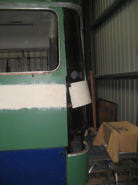
In the late summer there came a new vehicle to the vintage fleet, petrol powered mower SP75, which will be very useful in keeping the field under control, and make grounds-maintenance much quicker and more effective. That will make more time available for bus stuff. Now, in case you think that big stuff ain't happening, work has proceeded on a major hurdle to overcome at the rear end. It has long been my opinion that the panelling of the rear corners was not orientated correctly. In short, should the corners overlap the sides or vice-versa? It has not proved possible to find out from extant vehicles, but there is a strange feature in that area. The lowermost line of beading above the detachable panels for engine or radiator access does not continue around the corner. It ends at the vertical run which holds the front edge of the quarter panels, because if it continued it would cut across the rear lamp cluster. At the bottom there is no overlap because the quarter panels simply lap onto the strut which carries the panel hinge, and that means that the remainder of the quarter panel carrying the lamp cluster must continue to overlap the panels in the same sense. Honestly, I think this issue has caused me more grief than any other part of the job so far. Anyway, the bottom line is that I had to undo work that was done many years ago in order to make it work my way (even if it is wrong, it's the only way I can see to make it work). You can see this in the image below. By changing the overlap sense, the curved panels had to be fettled and trimmed to their new, dominant role, and it was tiresome. There is also the other problem that the lip on the beading which runs around the corner has to be removed because it runs onto plain panel which has a flat beading, and the general shortage of original thin-section beading meant that I had to slim down the thicker, modern pattern to match the original which it will eventually abut. By the time that all of this had been sorted I was not fit for much! I look forward to the day when the whole lot is ready for assembly.
**Footnote: |
|
BACK .......to the index. |
FORWARD .......to continue the diary. |


