
|
BPH 106H SM106 Restoration 2008 |

|
|
The Christmas-New year period provided few opportunities to work on SM106, despite an extended break, so it was a relief to find a slot on New-Year's Day. Fired up with the Boxing Day success on the START and STOP circuits, I tried to find how they interacted with the contactor unit. First stop was the small solenoid in the middle of the cab rear bulkhead, which had terminals labelled VSR and yes, the START circuit did go there, and was also cut off if the unit was 'energised' by finger-power. This is the interlock with the alternator, but I was suprised to find it so far from the control unit. Yes, its location is described in Maintenance Bulletin 53, but it's important to prove the point and not to take too much on trust. So what exactly was the big box, partly mesh-covered and marked "Clayton Dewandre Heater Unit, 12V" ? A complete red-herring is what it turned-out to be with its lid removed! It was a contacter, just as it should have been, but disguised in a spare box and wrapped heavily in electrical tape to hold the contacts closed. Once again, serious modification was revealed, but confusingly there was only one wire leading to the terminal strip with connections to the bus-bars in the cabinet beneath. Close inspection revealed a melted stub-end of wire - confirming that it had been a major electrical fault that precipitated all the mis-wiring. Exactly why no-one had the gumption to throw away the contactor and fit a switch (which is what I intend in the short-term) is anybody's guess. Holding the two thick wires from the terminal strip together allowed me to test the gear selection and the operation of the reversing-light solenoid. What a relief! Here ended a short, but pivotal work session.
Early January brought a mixture of fine, dry weather when it was possible to look at the panelling of the rear corners and offer up the shaped pieces that were in the stores, and gales the following week. Shredding of the tarpaulin that covered the front part of the bus allowed the water which drips from the hole in the barn roof access through the missing cab window once more. A reasonable step forward was to refit the cab window temporarily, and luckily I was able to find the weatherstrip among the parts stacked in the back of the bus. It looked fine, so it will be a wrench to have to remove it again in due course for continued work on the windscreen pan. Gales and driving rain have persisted for well over a week now, so I retreated to my garage with my sheet of 1.2mm aluminium and set about making a new nearside upper windscreen pan. The old was was not only battered, but had a 'Bus Stopping' sign inserted. Only the complexity of the shape, which has bends on three axes which meet at a point, has deterred me from starting sooner. The 'Ship' was pressed into service again, and this time a key feature was really important. In normal use, material is fed under the clamp between the bolts, but for special purposes one bolt can be omitted and a G-clamp used at the end. Bends can thus be made for only part of the total length, and in this case three bends come to a point to form a shallow box which makes clearance for the inwards protrusion of the windscreen top. It was a fiddle, but it came out right in the end, and fitted better than expected when offered up. The final tweak was with thumb and finger pressure to shape the curved corner where the metal had bulged under the stress of bending in conflicting directions. The sheet metal was as soft as butter when properly annealed. A trick that my late Uncle Leonard showed me (over 30 years ago) was to use the tail of a matchstick. If the metal is heated until you can write on it with the matchstick, it will be just right and can then be allowed to cool slowly. He used aluminium frequently in his model engineering, I suppose it was virtually free as he worked for British Aluminium, and knew all there was to know about working it. Fortunately, aluminium work-hardens so easily that it was good and stiff again by the time I had finished. It was really good to make progress again on an area that was progressing well when interrupted for the move.
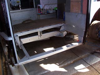
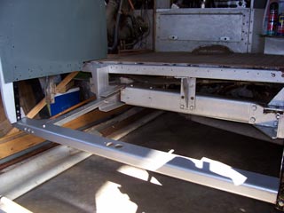
Removing the newly-remanufactured nearside, front chassis riser opened a bit of a can of worms. Painting it was quick and easy once it was taken indoors and the paint was warmed up a bit so that it would actually flow! Sitting with a cup of coffee and working out why it did not fit was more problematical. Parts with curved ends and angled flanges are very difficult to size up, but eventually it dawned on me that its position and height are set by the (upside-down) 'T'-shaped bracket which bolts onto the frontmost spring-hanger. It is then held level by attachment to the body-side rib just behind the front door. If the length is correct, it will sit with its inner flange in contact with the centre section of the riser. The error in fitting the new part had been to start in the centre of the bus and work outwards, rather than work inwards from the side. I shall be testing this theory when the holes drilled in the metal have been welded up and I have another go myself. For light relief after that I painted the new winscreen pan part and other cabside panels which have been removed for preparation. Once again, there is nothing like the smell of paint... Poor weather and a crisis in the extended family have conspired to keep me away from SM106 for a period of many weeks. The Llandudno Transport Festival was notable for my first ever attempt at driving a Bristol bus, and work on and around our house has kept me occupied apart from continuing little jobs that could be completed at home. One was fettling the parts for the riser replacement, and the other was finishing the manufacture of my new front destination blind. Cutting Fablon lettering to stick onto white Tyvek has occupied a good few evenings over the last year or so - but it's restful work while listening to my favourite radio programme: Late Junction on Radio 3. Finally it was time to stick down the letters and paint it over. The method is essentially a crib from Chiswick, but of course they used pre-cut letters to screen-print paper bills to stick onto the linen, and mine is a one-off. However it is authentic in the sense that all the lettering is cloned from a Chiswick original (mostly the WY front and rear donated by kind persons from their attics).
Anyway, back to the riser............ My contractor had removed and apparently forgotten the angle-bracket that interfaced the riser to the body rib, so it had to be replicated. The old bolt holes in the riser were mostly welded up and new ones positioned by measurement from the original part and drilled ex-situ using the attachments as a jig for correct postioning. In the end a bit of scrap steel 4mm thick was cut, curved and drilled to bolt inside the rib section, then the riser was inserted and attached properly to the spring-hanger bracket. Then the body side was pushed carefully inwards using the Matador as ballast until the rib touched the riser and they were tack-welded together. After dismantling again, Andrew welded the bracket onto the riser properly. It was then possible to insert the riser and mark where it attached to its inner section and take it home for ex-situ drilling. The entrance threshold does not hang from the body side, but instead from the riser by a shallow, open box. A new, extended box section had been fabricated by Blue Lake to carry the threshold at the lower level, so this was cut as appropriate and a new flange welded in the correct position for the original height. This time my neighbour Ian (Austin-Healey Sprite restorer extraordinaire) did the welding. At last on 18th May the metalwork was all brought together with a large stock of nuts and bolts for re-fitting in its proper place. The riser fitted well on the inner end and the hanger bracket, but was in the wrong place to fit the body-side rib. It is typical for a three-point fitting to only touch two of them simultaneously in the right place, so it became a jigsaw puzzle to work out which two to start with, so that the third could be 'manipulated' without upsetting the other two. Obviously it was the spring-hanger bracket which had to be detached from the chassis, because it is only held by two (larger) bolts. The riser itself connects to all its neighbours with (just) 24 quarter-inch bolts....Once freed, it was easy to attach the bodyside rib and draw it in with its six bolts. This left the awkward problem of how to get the canvas packing into a gap too small and the bolts through a pair of holes in the hanger bracket somewhat mis-aligned fore-and-aft. Solution - a scissor jack, some packing and a pry-bar to apply significant force to lift the body off the chassis sufficiently to manipulate the canvas packing into the gap. This left the problem of the bolts which hold the body down, and by then it had become obvious just how much force was required in that area. There was no convenient point to push against with a jack so I had a cup of coffee to celebrate being almost home and dry, and to apply some reasoning to the problem. With the bolts passing through the hanger bracket and the canvas packing, it was only necessary to move the whole riser assembly forward by less than 1/8 inch. I reasoned a little more with my large hammer and a lump of wood, carefully of course, to see if would deflect at all. It did, but under load it did not spring back, and two taps were sufficient to see the bolts drop home without any more persuasion being required. BINGO !!!! The rest of a pretty heavy day was spent attaching the threshold and the supporting arm which runs off the front chassis cross-member. There was also the curious, wedge-shaped bracket which supports the saloon-floor and its oblique outer edge, the shoe on the lower end of the nearside front corner post and another two dozen nuts and bolts of various sizes. With luck they will not require separating for a long while!
Once this hurdle was passed, the way was clear to install the new diagonal edge to the saloon floor. Old holes needed to be welded up as the fit had to be adjusted slightly, but it was not a big job to offer up, drill, fix and paint the new metalwork and cut a piece of scrap plywood to make a temporary floor extension. Sadly this was to prove the last major job completed before a major change of circumstances and vehicle movements brought to an end any useful work on this site. The only jobs completed from June onwards were to measure up and cut out the new 'Checkmate' plate to make the front step riser, to fit the engine-stop solenoid, injectors and leak-off gallery ready for checking over the fuel system. |


|
BACK .......to the index. |
FORWARD .......to continue the diary. |